

Welcome to a transformative journey in the world of smoking with the Masterbuilt electric smoker. Today, we are diving deep into the world of Proportional-Integral-Derivative (PID) controllers, specifically the Inkbird 106 PID kit, and how it can revolutionize your smoking experience by offering unparalleled temperature precision.
This guide will walk you through assembling the PID kit and modifying your Masterbuilt smoker for optimal performance. For a more detailed PID controller setup guide, check out our comprehensive walkthrough.
Note: most links in this article are Amazon.com Affiliate links, see Affiliate Disclosure, thank you.
Introduction to PID Control
The challenge with most electric smokers, including the Masterbuilt series, lies in their inability to maintain precise temperatures. They often overshoot the desired temperature and then dip below it, creating a wide temperature “swing” that can affect cooking consistency.
A PID controller addresses this issue by maintaining a tighter temperature range, enhancing your cooking results.
Safety First
Before we begin, it is crucial to address safety, especially when dealing with electrical components. If you are uncomfortable with electrical wiring, consider purchasing a pre-assembled PID controller. I have years of experience wiring, car alarms, stereos, boats, subpanels, and computers.
Always prioritize safety by using components rated for the correct amperage and ensuring your setup is plugged into a GFCI outlet.
Assembling the Inkbird 106 PID Kit
The assembly process involves several key components: the PID controller, a 40 amp SSR (Solid State Relay), a heat sink, a retainer for the PID, and a K-type thermocouple.
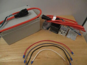
Component Overview
- PID Controller: The brain of the operation, managing the temperature based on input from the thermocouple.
- Retainer: Secures the PID controller within the assembly box(included with PID).
- 40 Amp SSR: Acts as a switch controlled by the PID to regulate power to the smoker’s heating element(included with PID kit).
- Heat Sink: Dissipates heat from the SSR to prevent overheating(included with PID kit).
- K-Type Thermocouple: Measures the temperature inside the smoker, providing real-time data to the PID(included with PID kit).
- Thermal Paste: Allows heat to transfer freely from the SSR to the heat sink.
- Junction Box: Holds components and contains wiring.
- 14 GA Wire: 4 pieces of 14-gauge wire to connect the components.
- U Type Wire Terminals: Add to wire for secure connections.
- Female Quick Disconnect Terminal: Add to wire for smoker element pigtail.
- 14 GA Extension Cord: Connect input and output 120-volt power.
- 14 GA Power Cord: Pigtail connection from smoker element to PID output power.
- 3/8″ Clamp Type Cable Connectors: To secure the input and output 120-volt wires.
- 2 – #8 Bolt, Nut, Washer: To mount the heat sink to the junction box.
Step 1: Preparing the Enclosure
Place the PID and the heatsink on the inside of the lid close together without touching. Ensure the heat sink is positioned with the feet side against the box lid and the smooth side up. Trace around the components with a fine tip sharpie to mark the location.
Mark two locations in the lower corners large enough for the 3/8″ wire clamp. Mark one location in the upper corner on the PID side large enough for the Thermocouple wire terminals to pass through.
Note: For this project, I chose the Inkbirdplus plastic junction box; it is rugged and well-priced.
Step 2: Cutting and Fitting
Cut the square opening with an oscillating saw to the minimum size to insert the PID. The flange on this component is small, so do not over-size the opening. Drill the two holes to mount the SSR heat sink, then install both components.
Check the fit and spacing before drilling the three holes, and drill the holes once confirmed. A step bit is an excellent attachment for your drill to get a sound hole in the plastic. Install the 3/8″ wire clamps in the two lower holes.
Step 3: Installing the SSR
Put a small amount of thermal paste on the heat sink on the heat sink. Place the SSR on the heat sink with the input terminal toward the top of the junction box and attach it with the included machine screws. Tighten each screw evenly so the thermal paste will spread evenly.
Make sure the screws are tight but do not over-tighten them.
Step 4: Prepare the Wires
Check the U-type terminal to ensure they will fit the PID and SSR terminals. Cut four wires to six inches in length. Then, add one terminal to one wire (white one) and two terminals to the others.
Cut the extension cord in half and strip the out coating six inches back, exposing the three wires without damaging them. Add U-type terminals to the black wire, then strip the remaining wire back roughly 3/8 of an inch.
Tip: Using different color wires can help you track which wire goes where. Typically, I use standard wire colors such as white for neutral, green for ground, and black for hot. I used red, blue, black, and white 14-gauge wires for this project.
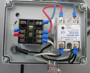
Step 5: Wiring the Components
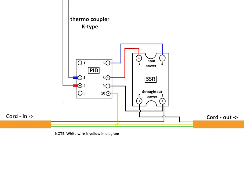
Start by connecting the wires near the center of the units, as the connections get tricky after you have more wires in the way. Other than that note, follow the included wiring diagram or my color code diagram, and you will be fine. Here is my step-by-step procedure for how I like to connect the wires.
A: Connect PID terminal 8 to SSR input terminal 3, then PID terminal 6 to SSR input terminal 4. These connections must be correct, or the SSR will not operate.
B: Next, connect PID terminal 9 to SSR terminal 1.
C: Feed the Thermocouple terminals through the smaller upper hole and attach the PID blue to terminal 3 and red to terminal 4.
D: Connect the wire with one U-type terminal to PID terminal 10.
E: Feed the cut extension cord through the 3/8″ wire clamps so the terminals are on the inside of the junction box. Connect the input cord terminal to SSR terminal 1 and the output cord terminal to SSR terminal 2.
F: Join the two green wires and the three white wires. Using a wire nut is a best practice to join these wires, but you can also use a Wago or black electrical tape.
Note: Depending on the position you would like the PID Controller to be on the smoker, you might want to reverse the holes used for the power cords.
Modifying the Masterbuilt Electric Smoker
Modifications to the Masterbuilt smoker are necessary to utilize the PID controller. This section guides you through attaching a pigtail cord to the smoker’s heating element and ensuring proper grounding.
If you’re interested in enhancing your smoke flavor with charcoal, we have a creative solution for an authentic barbecue taste.
Step 1: Accessing the Heating Element
Turn off and unplug the smoker. Remove the heating element cover.
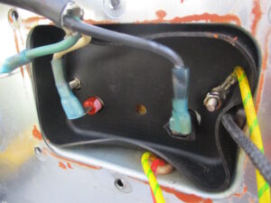
Step 2: Attaching the Pigtail Cord
Prepare a pigtail cord with appropriate terminals. I prefer a heat shrink ring terminal on the green wire and two female quick disconnect terminals on the other wires. Disconnect the black and red wire from the heating element.
Connect the two female quick disconnect terminals to the heater element terminals. Connect the ring terminal to the bolt terminal or to the body of the smoker with one of the cover plate screws.
Note: If you would like to drill a hole in the cover and use a 3/8″ wire clamp, do so before connecting the pigtail so you can feed the wire through.
Step 3: Reassembling the Smoker
Once the pigtail cord is securely attached and grounded, reassemble any components removed during modification. Ensure all connections are secure, the disconnected wires are safely pushed into the cavity, and the panel covering the heating element is replaced.
Step 4: Installing the Thermocouple
Typically, you can run the wire upward from the bottom of the door and set the thermocouple on one side of the cooking shelf for great results. But if you want a more permanent installation, we recommend buying a 50mm tube-length K-type thermocouple and drilling a hole in the door slightly higher than the primary cooking shelf.
Use care if you choose to drill the hole through the side of the smoker because there could be wires inside the smoker’s body. Regardless of which route you go, avoid touching the sensing probe of the thermocouple on anything for an accurate reading.
Testing and Adjusting the PID Controller
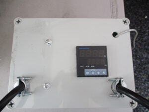
It’s time to test the setup with the PID kit assembled and the smoker modified. Connect the PID controller to a power source and the pigtail cord from the smoker to the PID. Insert the thermocouple into the smoker, ensuring it’s positioned to measure the internal temperature accurately.
Discover the secrets to optimal wood chip usage in your Masterbuilt smoker for perfect smoking results.
Step 1: Initial Power-Up
Power on the PID controller and observe the initial readings. Adjust the temperature to your desired smoking temperature, monitoring the PID’s response.
Step 2: Fine-Tuning
Based on the initial test, you may need to adjust the PID settings to achieve the desired temperature control. This involves fine-tuning the PID parameters (P, I, D settings) to match the heating characteristics of your smoker.
Step 3: Continuous Monitoring
During the first few uses, closely monitor the temperature stability and make adjustments as necessary. Note any temperature “swing” and adjust the PID settings to minimize it.
Conclusion: Elevating Your Smoking Game
By integrating a PID controller with your Masterbuilt electric smoker, you’ve taken a significant step towards precision smoking. This setup allows for tighter temperature control, reducing the temperature variations affecting cooking outcomes.
With patience and practice, you’ll be able to achieve consistent, repeatable results, elevating your smoking game to new heights. Remember, the key to success with this project lies in careful assembly, meticulous modification, and continuous adjustment based on performance.
Embrace the process, and enjoy the journey to becoming a master of precision smoking.